ATW-0512 Technical Details |
Tube design wall-mounted automatic sensor tap with under mount infra red eye
- Features
- Technical Details
- Dimension
- Contents
- Special Notes
- Temperature Control
- Remote Control
Features
Wall-mounted sensor tap
230mm Length
Under-mount sensor eye
Conserve water and Hygienic
Power Options: Mains/4XAA Alkaline batteries (up-to 2yr lifespan)
Hands free infrared activation
Stylish tube design
Solid brass construction
Finish: Chrome-plated
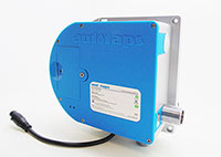
Control box type: ACB-0112
Special Notes:Water pressure:
Water pressure range: 0.7 (Min) - 8 Bar (Max) (1 bar or above for best performance)
QUICK VISUAL DATA
 |
 |
 |
 |
| Sensor tap can be powered by both Mains (AC) and Batteries (DC) | Sensor tap comes with a single water supply feed | 26mm | Control box for this sensor tap is supplied with detachable UK 'fused' plug |
TECHNICAL DETAILS
Control box: Diameter of 'inlet' pipe: G1/2”
Control box: Diameter of 'outlet' pipe: G1/2”
Water pressure range: 0.75 (Min) - 7 Bar (Max)
Voltage: DC6V or AC220V-240V (6V Output)
Power consumption: =0.3mW
Sensing distance: 6-24cm
Respond time: 1 Second
Battery Consumption (DC): 4xAA alkaline batteries (up-to 2yr lifespan depending on level of usage)
Silent Consumption: 0.003mW
Environment Temperature: 1-45 C
Flow Rate: 6L/Per minute
Pipe Threading: British Standard Whitworth (BSW)
Noise Class: 1
Finish: Chrome-plated
Voltage: DC6V or AC220V-240V (6V Output)
Power Options
DC = Direct Current (Battery source)
AC = Alternate Current (Mains electricity supply)
DC only: The tap can run off batteries only (4 x AA batteries)
We recommend using alkaline batteries, which should be new and of the same brand.
AC only: The tap can run off Mains power supply only.
A 'step-down' transformer is supplied,
type AC220V-240V (with 6V Output)
AC + DC: The tap can run off both AC (Mains) + DC (Batteries) connected at the same time.
This means, AC (Mains supply) will run the tap as normal, while the DC (batteries) ramains dormant, and acts as a backup power should the AC power fails.
TIP:
It's entirely up to you to decide which power option/combination suits your installation/usage the best.
The integrity of the tap stays the same.
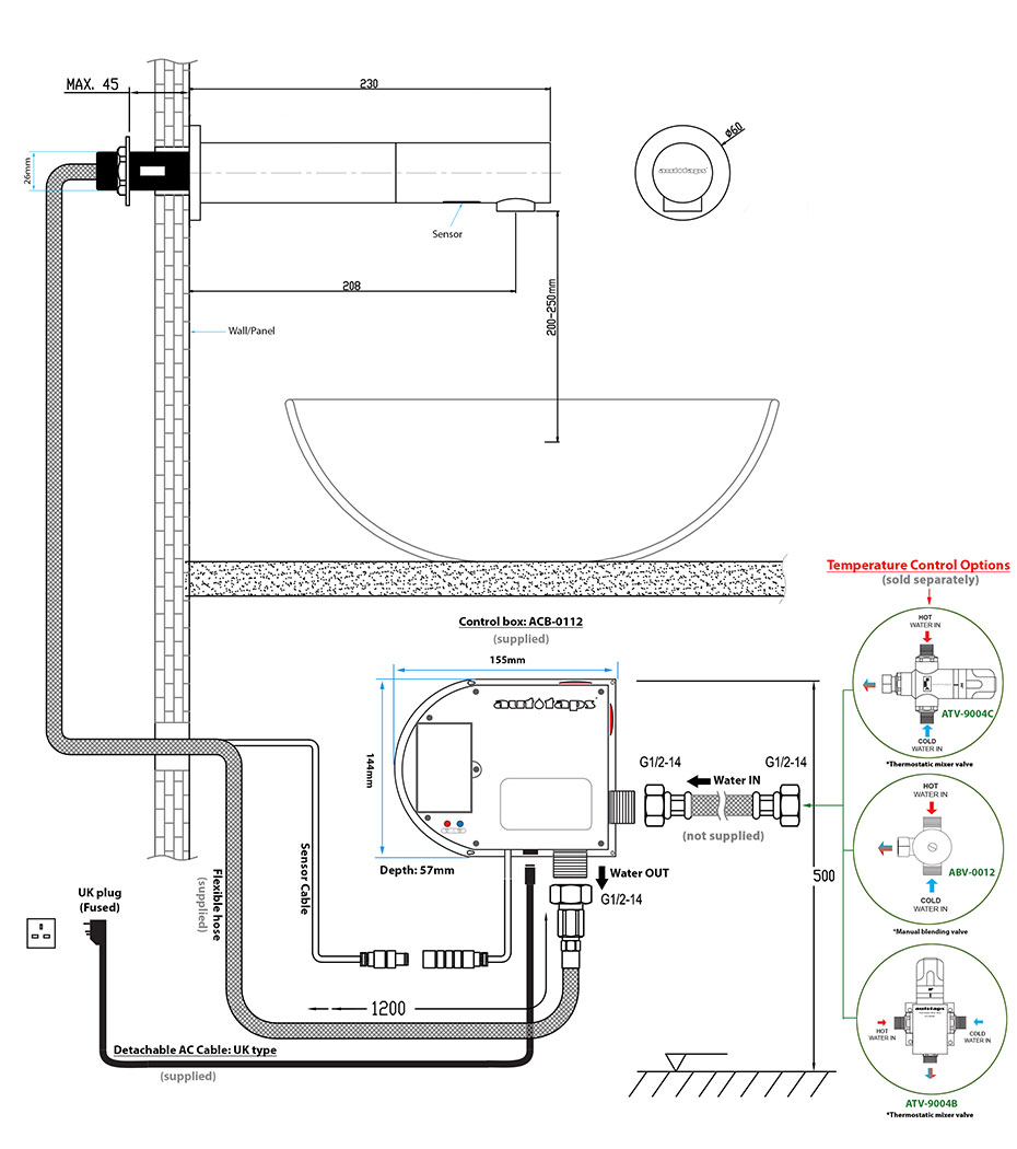
DIMENSION:
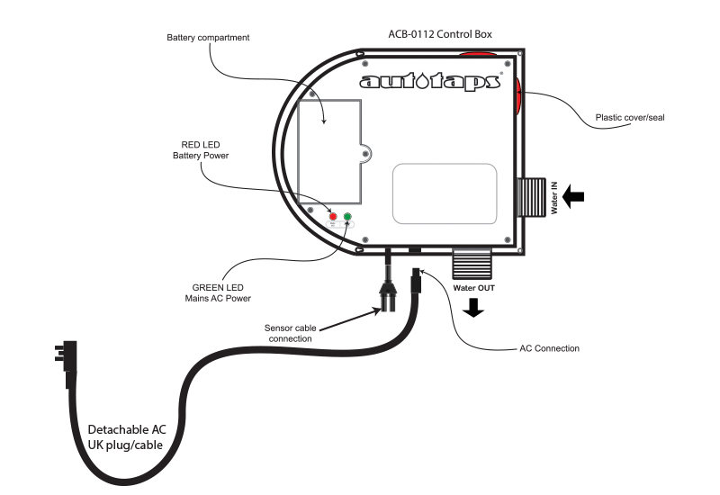
Control box Features
Front View
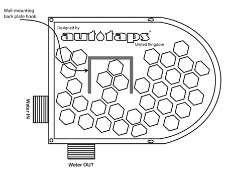
Back View
CONTENTS
1x Sensor Tap (with flexible hose attached)
1x Control Box (*battery compartment inside)
1x AC cable (UK plug)
1x Transformer (Built inside control box)
1x Control box 'wall-mounting' clip
Fittings and Screws
SPECIAL NOTES
YOUR CHOICE OF ACCESSORIES
In general, accessories i.e. sinks or basins are made using different types of materials and finishes, and some of these materials can trigger an infra red sensor to act abnormally. Please make sure that any accessory you've chosen is compatible with an infra red sensor. Please note that customer's choice of accessories are outside the scope of our company's liability, and we cannot accept any responsibility for any discrepancies, refunds, faults, malfunctions, cost of installations/removal arising from such situation.
SHINY/REFLECTIVE SURFACES
Highly reflective or shiny surfaces of some accessories i.e. sinks can cause the sensor to function incorrectly i.e. cause the sensor to false trigger or operate intermittently. Please make sure your choice of accessories are compatible with an infrared sensor.
NOTE:
Only few percentage of these surfaces do cause problems, in most cases (95%+ of the time) the taps works perfectly. We are only highlighting this problem because it does happen and we have the obligation to tell or make our customers aware of these types of issues.
TIPS:
In many cases, it's not the basin that's causing the reflection but it's the 'waste trap' reflecting the light, which in turn interacting with the sensor.
You can try the following:
1. Reduce the proximity sensing distance to a lower range.
2. Move/reposition the basin so that the sensor is not pointing directly unto the waste trap.
3. Change the waste trap to a 'non-reflective' or matte finish type.
4. Opt-in for a 'wall-mounting' sensor (pointing forward) instead.
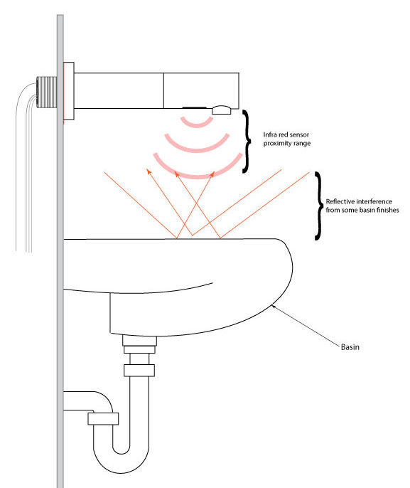
Water pressure:
Water pressure range: 0.7 (Min) - 8 Bar (Max) (1 bar or above for best performance)
Temperature control:
This sensor tap is designed to be supplied with pre-mixed water.
Consideration should be given to safe hot water delivery and the use of an appropriate temperature reduction device.
See images below.
Manual blending valve:
ABV-0012
Water temperature is controlled manually.
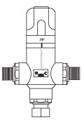
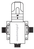
Thermostatic mixer valves:
ATV-9004B
ATV-9004C
Water temperature is regulated automatically.
Frequently asked question:
Question:
What's difference between 'ATV-9004B' and 'ATV-9004C'?
Answer:
They're litterally both the same thing, except for only one difference.
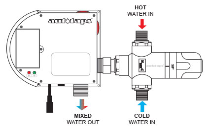
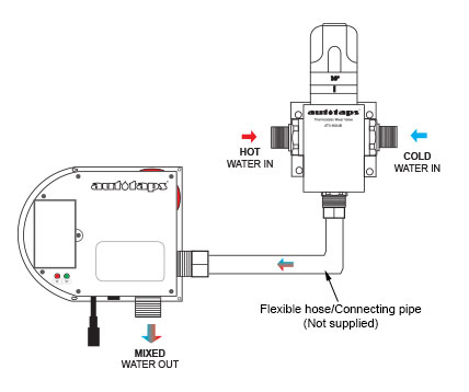
ATV-9004B has a 'wall-mounting' brackets attached to it, while ATV-9004C has a 'female' connection end, which can be connected directly to a control box 'inlet' as shown below.
|
Option 1: ATV-9004C
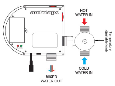
This thermostat can be connected directly to the control box using its 1/2" female outlet connector. This method is usually the quickest way to setup installation. |
|
|
|
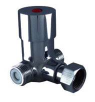
Option 4 : ABV-0012
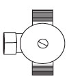
This is a manual blending valve only, adjustable by hand. There's no thermostatic mixing element inside. Any desired temperature can only be achieved 'manually' by turning the knob clockwise or anti-clockwise by hand. |
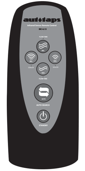
Infrared Remote Control: IRC-6.13
Sold separately |
 |
FLUSH/RUN Water: Flow Time Increase HOW TO: NOTE: |
 |
FLUSH/RUN Water: Flow Time Decrease HOW TO: NOTE: |
|
|
Increase Sensor Distance HOW TO: *Sensor distance range scope is around/between 7cm-35cm |
|
|
Decrease Sensor Distance HOW TO: *Sensor distance range scope is around/between 7cm-35cm |
|
|
Auto Search |
|
 |
Standby To disable, press once, LED light comes on and stays on for 2-3 seconds ‘twice’ and then goes off. Standby mode is now disabled. |

